
How to Reduce Metal Stamping Costs: 5 Real Tips from a Fabrication Factory
Over-specifying tolerances, choosing highly rigid materials unnecessarily, or designing complex bends that require secondary operations can drive your custom sheet metal stamping costs up by 25% to 45%. In high-volume progressive die stamping, these design oversights multiply into thousands of dollars in wasted material and tool maintenance fees.
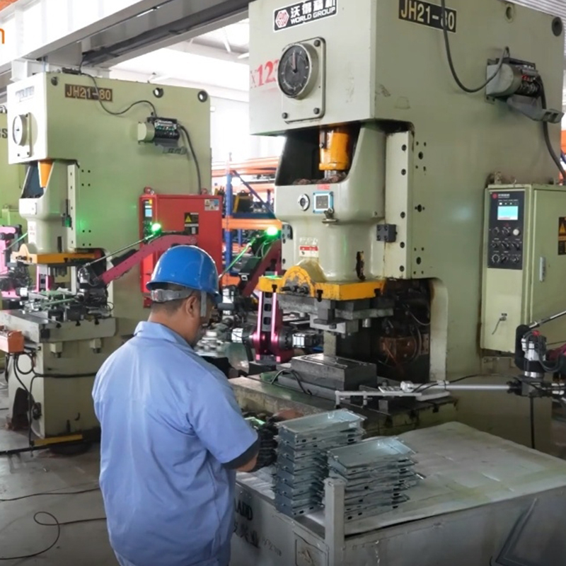
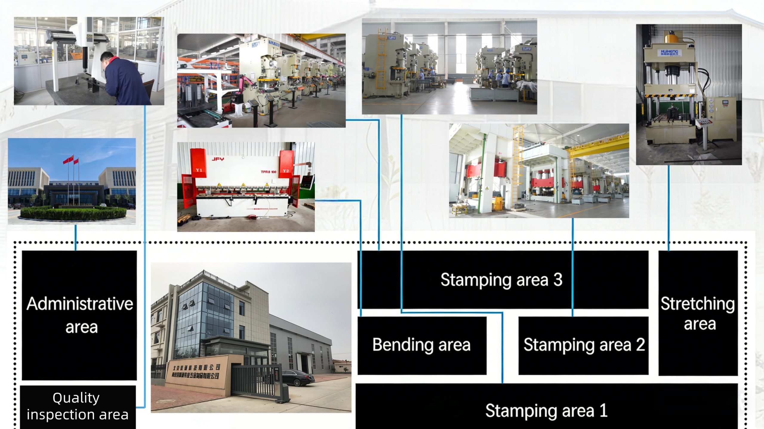
As a metal fabrication factory with over 25 years of industry experience, we review hundreds of blueprints monthly. We see hardware purchasing managers and product designers paying unnecessary premiums every single day. True cost-efficiency is achieved during the initial Design for Manufacturability (DFM) stage, not through raw material haggling. Here is how our engineering team optimizes component designs to significantly slash your metal stamping budget.
1. Optimize Internal Bend Radii to Match Material Thickness
One of the most common mistakes in sheet metal component design is specifying an internal bend radius ($R$) that is too sharp or completely inconsistent. When the internal bend radius is smaller than the material thickness ($t$), the material undergoes severe stress concentration, leading to outer surface cracking, torn corners, and rapid tool wear.
To ensure high reproducibility and eliminate secondary annealing processes, always maintain a rule of thumb: keep the minimum inside bend radius equal to or greater than the material thickness ($R \ge t$). Furthermore, maintaining uniform bend radii across the entire part allows the stamping facility to utilize standard radius tooling in a single sequence, eliminating expensive custom tool grinds and extra station setups within your progressive die.
2. Respect the Proportions of Hole Diameters to Material Thickness
Punching holes is the fastest and most economical way to create openings in metal stamping. However, pushing standard stamping presses beyond physical limitations causes premature punch breakage and severe part deformation. A frequent error is designing tiny holes in thick, high-strength metals.
For reliable high-speed production, the diameter of any punched hole ($D$) should never be less than the material thickness ($t$), expressed as $D \ge t$. If you are stamping tough alloys like AISI 304 stainless steel, the ratio should be increased to $D \ge 1.5t$. Additionally, the web distance (the spacing between the hole edge and the part edge, or between two adjacent holes) must be kept at a minimum of $2t$. Violating these spacing guidelines results in material distortion and a weak die skeleton that requires frequent downtime for repairs.
3. Select the Most Machinable Material Class for Stamping
Material choice represents up to 50% to 70% of the total cost of a stamped metal part. Product engineers frequently over-specify material grades out of caution, choosing highly expensive or hard-to-form alloys when standard commercial grades would perform perfectly. Harder metals require higher tonnage presses, consume more energy, and accelerate die wear.
Consider the following comparison table when balancing structural integrity with manufacturing costs:
| Material Group | Common Grade | Formability & Stamping Ease | Tooling Wear Factor | Cost-Efficiency Strategy |
| Aluminum Alloys | Al 5052-H32 | Excellent formability; minimal springback. | Very Low | Highly recommended for lightweight enclosures; reduces tool maintenance. |
| Carbon Steel | SPCC / CRS | Highly ductile; predictable forming limits. | Low to Medium | Best value for automotive brackets; requires plating/coating. |
| Stainless Steel | AISI 304 | High work-hardening rate; requires high press tonnage. | Very High | Use only when strict anti-corrosion standards are mandatory; increases tool costs. |
| Copper Alloys | C11000 (Pure) | Highly malleable; clean shear edges. | Low | Ideal for electrical terminals; keep geometries simple to minimize raw material scrap. |
4. Avoid Complex Flanges and Overly Narrow Tabs
Intricate, multi-stage contours and narrow tabs look great in 3D CAD software, but they introduce major friction in real-world stamping manufacturing. Narrow, projecting projections (tabs) on a part are highly vulnerable to bending and fracturing during the blanking and ejection stages. As a rule, ensure that tab widths are at least twice the material thickness ($W \ge 2t$).
Similarly, complex, curved flanges that stretch or compress the metal excessively will trigger wrinkling or localized thinning. If your part requires a flange for structural rigidity or assembly, try to design linear, straight flanges. When complex geometries are unavoidable, incorporating small relief notches at the intersections of bends can eliminate the stretching stress, avoiding the need for secondary trimming tools.
5. Relax Tolerances on Non-Critical Features
Nothing inflates progressive tool build costs faster than tight tolerances across non-mating dimensions. Specifying a precision tolerance of $\pm0.05\text{mm}$ on a simple clearance cutout or an outer structural profile forces the metal factory to build micro-adjustable die modules, implement expensive in-die optical measurement systems, and slow down the press strokes per minute (SPM).
For standard high-volume stamping, adopt commercial tolerances of $\pm0.13\text{mm}$ to $\pm0.25\text{mm}$ for linear dimensions and $\pm1.0^{\circ}$ for bend angles wherever possible. Reserve precision tolerances ($\pm0.03\text{mm}$ or tighter) strictly for critical alignment holes, press-fit sectors, and operational mating surfaces. Relaxing non-mating specs reduces initial tooling investment by up to 30% and extends the lifespan of the tool between sharpening cycles from 50,000 hits to over 200,000 hits.
Conclusion: Send Your Designs for a Free Factory DFM Review
Substantial cost reduction in precision metal stamping is not about compromising the quality or safety of your finished product—it is about designing with the limits and behavioral mechanics of stamping tools in mind. By standardizing internal bend radii, matching hole diameters to stock gauge, choosing practical materials, and maintaining commercial tolerances, you can achieve drastically lower per-part costs and seamless, high-speed production runs.
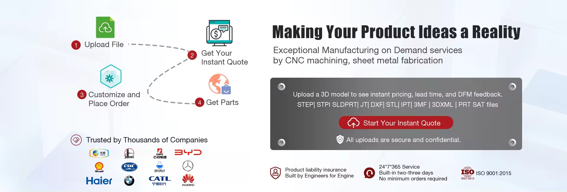
Ready to validate your next sheet metal project for optimal cost-efficiency? Upload your native STEP, IGS, or SolidWorks (.sldprt) files to our technical department today. Our production engineers will provide a complimentary Design for Manufacturability (DFM) assessment and deliver a comprehensive manufacturing quotation within 24 hours.