


Introduction: The Rising Demand for Burr-Free Stamping
As industries like EV manufacturing and microelectronics demand near-perfect component tolerances, burr control in metal stamping has become a critical quality benchmark. The global market for precision stamping parts continues to grow, with burr-related defects costing manufacturers up to 12% in scrap rates.
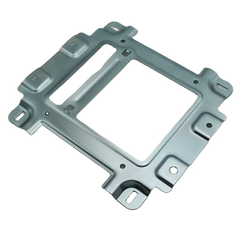
Section 1: Industry Challenges & Burr Formation Mechanisms
1.1 Root Causes of Burrs in Metal Stamping
- Material Factors:
High ductility alloys (e.g., aluminum 6061, copper C11000) prone to microburrs during shearing. - Tooling Wear:
Progressive die degradation causes edge fracturing and burr height >0.1mm (critical threshold for aerospace components). - Process Parameters:
Incorrect punch-die clearance (±5% optimal range) increases shear zone irregularities.
2.1 AI-Driven Tooling Optimization
- Adaptive Press Control:
Real-time adjustment of stamping force (±2% accuracy) using IoT-enabled presses. - Predictive Maintenance:
Machine learning models predict die wear 48hrs in advance, reducing burr recurrence by 70%.
2.2 Advanced Deburring Techniques
- Laser Deburring:
Fiber lasers (1,064nm wavelength) remove sub-10μm burrs on titanium medical implants. - Electrochemical Deburring (ECD):
Achieves Ra <0.4μm surface finish for copper connectors in 5G devices.
2.3 Material Science Innovations
- Nanocoatings for Dies:
TiAlN-coated punches extend tool life by 300%, reducing edge chipping. - Process control: In high-speed stamping, burr formation is reduced by holding the correct punch to die clearance, keeping the cutting edges sharp and the dies aligned.
Related capabilities
We produce parts of this type with custom metal stamping. We also manufacture for Electronics and electrical and Medical and laboratory programmes.
What burr control applies to
Burr control matters wherever a stamped edge has a function. It applies to mating faces that have to sit flat, connector and contact edges in electrical parts, medical and laboratory components that will be handled, and any assembly where a raised edge would interfere with fit or damage a mating part. Where the edge condition is critical, the burr is designed out rather than removed afterwards: the punch and die clearance is set for the material, cutting edges are kept sharp, the dies are aligned, and the tooling is built so the shear happens cleanly instead of tearing.
Where a truly square, fully sheared edge is needed in one stroke, fine blanking with a counter pressure ring produces it and removes the need for secondary machining on the cut face. Where the part is stainless and will be handled, deburring and passivation are standard and remove the free iron left by tooling contact at the same time. Surface finishing such as zinc plating, powder coating or anodising follows, with the coating thickness range specified so the finish does not close out a critical hole or thread.
What to send for a stamped part quote
Send the drawing as a DXF, STEP, STP, SLDPRT, PDF or DWG file, with the material grade, the strip thickness and the annual volume. The annual volume matters more than the first order quantity, because it decides the die type and how the tooling cost is recovered in the piece price. Also state the edge condition: whether burr height is limited, which faces must sit flat, and whether the part will be plated or passivated afterwards. The quotation, tooling price and per piece price are returned within 24 hours.
What affects cost and lead time on stamped parts
Tooling is the first cost and it is quoted separately from the part price so a buyer can see exactly what is being bought. The die type follows the volume: below roughly 1,000 pieces the tooling rarely pays back against laser cutting and bending, and above roughly 5,000 to 10,000 pieces a progressive die normally wins on total cost, with part complexity deciding the ground in between. Die wear is a real cost driver on long runs, so the maintenance interval is set from the critical dimensions rather than from a fixed calendar. Stamping itself is fast once the die is proven, so the lead time lives in tooling, first article approval and material call-off, not in press time. There is no minimum order quantity at any stage.
Tolerances achievable on stamped parts
Plus or minus 0.02 mm on critical features is the normal working tolerance on stamped parts. Tighter is possible on selected dimensions with a dedicated die, but it has to be engineered in from the start because it depends on the die build rather than on an adjustment made later. Stamped parts hold their geometry because the shape lives in the tool rather than in the operator, and because the process introduces no thermal distortion, unlike welding. Where a burr limit is specified, it is treated as a controlled characteristic and checked with the same dimensional discipline as the profile.
How stamped parts are checked
Incoming strip or sheet is verified against the mill certificate before it is released to the press. In-process checks track the critical dimensions and the edge condition across the run, not only at the first piece. Final inspection produces the report that ships with the order: a CMM dimensional report, a first article inspection report, an EN 10204 material certificate, coating thickness readings and hardness results where heat treatment is involved. A first article is submitted for approval before the batch runs to volume, and third-party inspection by SGS, TUV or BV can be arranged at any point. Where your quality department needs a specific record format, the request goes into the enquiry and the report is matched to it.
Common mistakes buyers make with stamped parts
The usual mistakes are ordering a die for a volume that will never recover its cost, specifying a tighter tolerance than the function needs, and forgetting that die wear changes the edge over a long run. Another is approving a first article without checking the burr condition, and then discovering at assembly that the edge interferes. Leaving the material grade open is also costly, because the strip grade decides the clearance and how much springback has to be compensated in the die. Sending the drawing together with the annual volume and the edge requirements removes most of the guesswork before the tooling is committed.
Key facts
| Item | Detail |
|---|---|
| Press range | 25 to 400 tonnes, covering progressive, compound and transfer dies |
| Tooling | Dies designed and built in our own tool room rather than subcontracted |
| Tolerance | ±0.02 mm on critical features; tighter on selected dimensions with a dedicated die |
| Burr control | Punch to die clearance, sharp cutting edges, die alignment, lubrication and tooling condition |
| Deburring | Deburring and passivation are standard for stainless parts; fine blanking gives a fully sheared square edge |
| Inspection | First article inspection plus verification of critical dimensions on a CMM |
| Company experience | 28 years in metal stamping and sheet metal fabrication |
For independent technical reference on the standards that apply to metal products and test methods, see ASTM International.
Frequently asked questions
What tolerance can be held on a stamped part?
Plus or minus 0.02 mm on critical features is the normal working tolerance. Tighter is possible on selected dimensions with a dedicated die, but it has to be engineered in from the start rather than requested after the die is built.
What causes burrs in metal stamping?
Burrs come from three places. Material that is soft and ductile, such as aluminium 6061 or copper C11000, tears rather than shears cleanly. Tooling wear lets the punch and die edge degrade. And incorrect punch to die clearance leaves an irregular shear zone, so the clearance is a setting to be held rather than a one time choice.
How are burrs removed from stamped parts?
Deburring and passivation are standard for stainless parts that will be handled or that need a clean cut edge, and the same step removes the free iron left by tooling contact. Where a part needs a fully sheared square edge in one stroke, fine blanking with a counter pressure ring removes the need for secondary machining on the cut face.


